Building the Solder : Time Desk Clock

I've been having a great time assembling some of the kits from Spikenzie Labs over the past few weeks. Yesterday, I wrapped up one of the more soldering-intensive projects that I've done -- the Solder : Time Desk Clock! I've done a little work with LCD screens and socketed ICs before, but nothing this large. Here's a few shots from the build log, along with some pointers if you decide to build the kit for yourself.
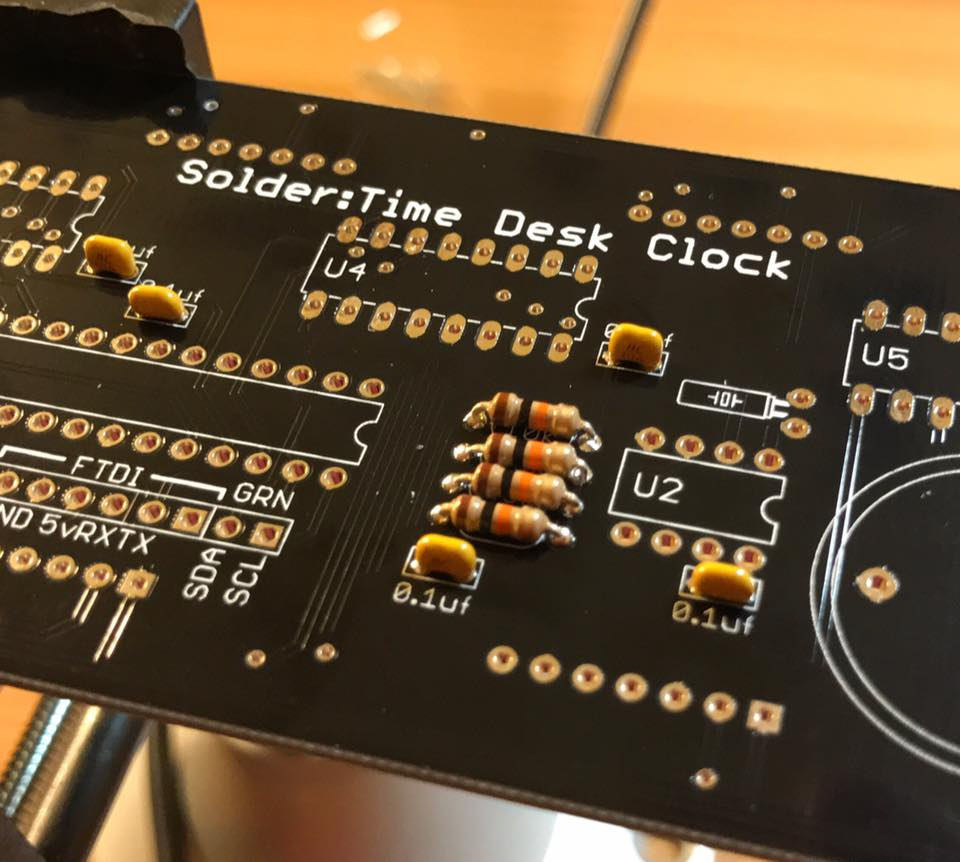
First things first, we need to get the capacitors and resistors installed! I always have trouble telling resistors apart -- I have protanopia, which means reds, oranges, and yellows are way less vibrant for me. Purples and violets are had to distinguish from blues as well. To get around this problem, I usually keep all resistors of a particular type bagged and labeled and just fetch them when I need to. I eagerly await the day when someone cooks up a "photo ID" app for iOS that can translate the bands on the fly!
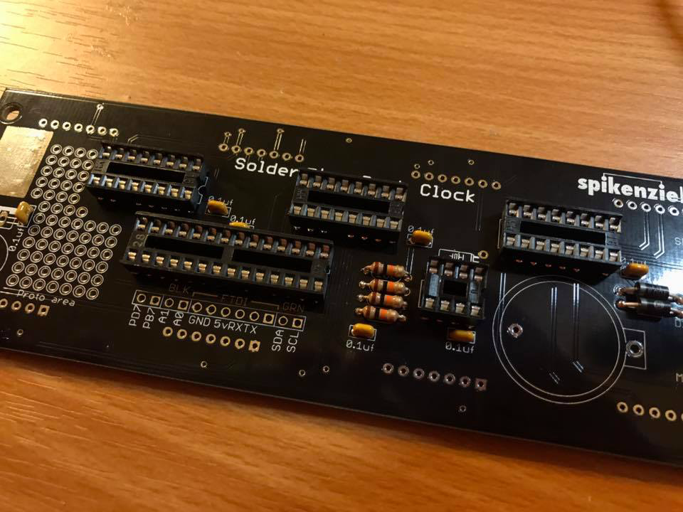
Jumping ahead a little bit, we have the same board, but now all of the sockets for the integrated circuits are installed. This makes it easier to replace the ICs if something breaks! There are a couple of benefits to using integrated circuits:
- A much smaller board -- every IC is a collection of transistors and other components that would take up a lot more space if they weren't printed on to a chip!
- Cost -- ICs are usually cheaper than the cost of all of the discreet components you'd have to buy if you wanted to make the circuit "from scratch!
- Ease-of-use -- once you figure out how to build something like a timer, it's nice to just be able to pop a chip in to replicate it (think of how much soldering you'd need to do for three or four timers)!
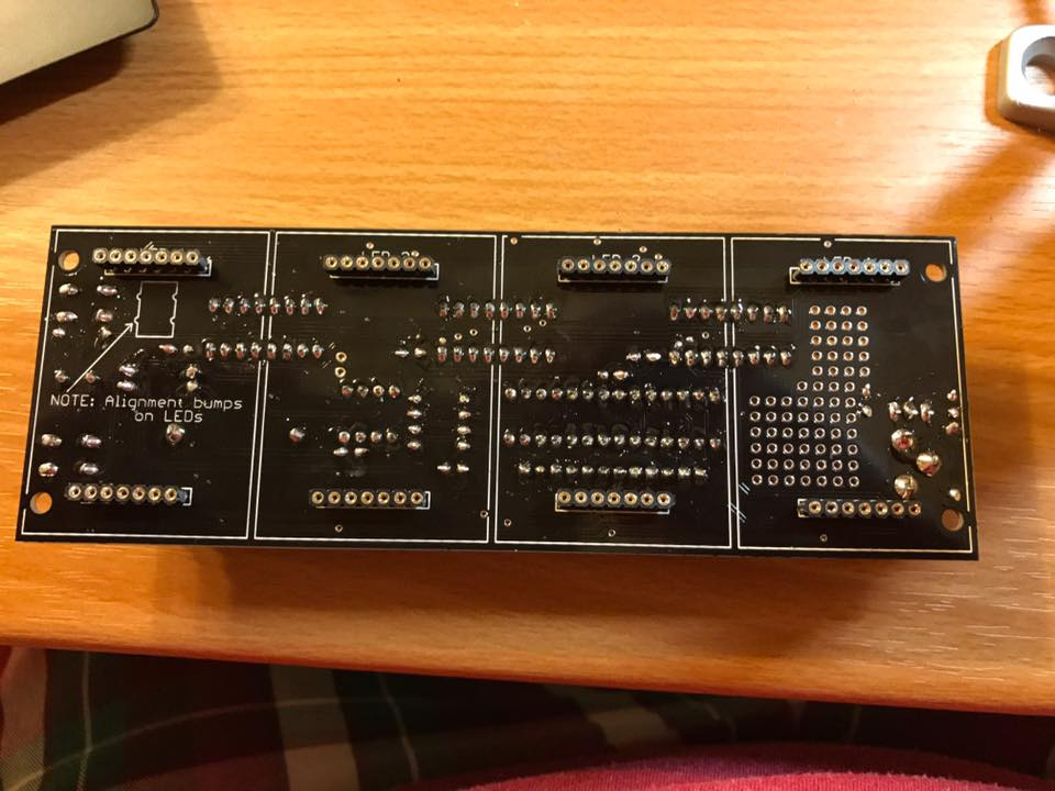
Since we need to display numbers on our clock, we need screens! Since displays tend to be fragile (I've certainly destroyed a few), we're going to make them easier to install and replace by soldering in some female headers. We'll use them a bit like the IC sockets we installed earlier; instead of soldering each display in to the board, we'll pop them in to these makeshift sockets instead. A word to the wise -- I highly recommend putting the female headers on the displays, then soldering them in with the display already installed. Getting everything to line up perfectly without the displays in place is a huge pain in the butt!

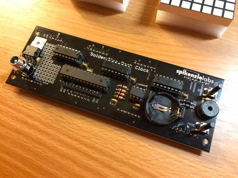
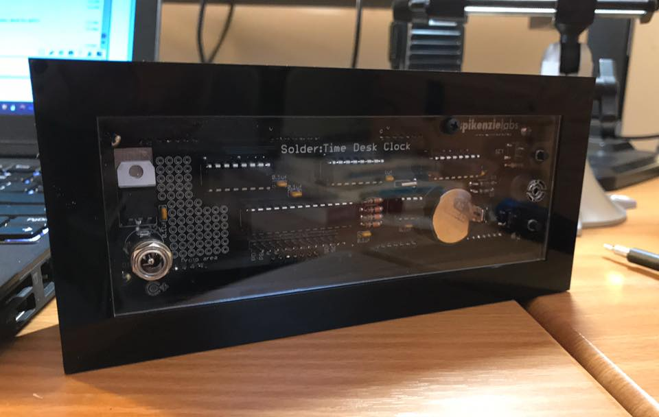
Okay! Now we have everything installed on the board except the screens! The bits on the left edge are the power socket and voltage regulator -- we're going to power this off of a wall wart! Moving across the board, the sea of tiny holes is a prototyping area. I didn't do anything with it on this clock, but you could install all sorts of things in this space. Next, we've got all of our integrated circuits from earlier. I've installed them all in their sockets and soldered in a 12-pin header in case I want to re-program anything at a later date. The header's just below the longest integrated circuit. Wrapping things up is a CR2032 battery holder; this is so the clock doesn't forget the time if it's unplugged (handy), the set/mode switches, and a tiny speaker for the alarm feature.
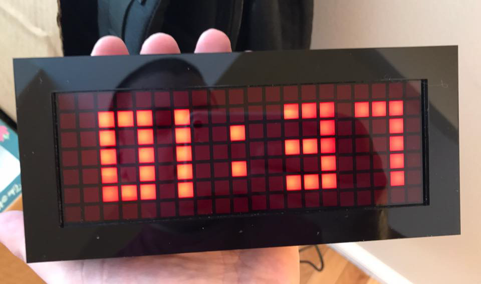
Hooray, the circuit is good! Remember, always test your project before you install it in a case!
The case for the clock is made out of my least-favorite material, piano black acrylic! I understand that cost is a big driver here, and the fact that acrylic doesn't conduct electricity makes it easier to mount boards and circuits. However, this particular acrylic suffers from two major flaws: it's not strong, and it's a huge fingerprint/scratch /dust magnet. You can't see it in these photos because of the "cosmetic panels" I have surrounding the frame, but I cracked the rear frame panel in four places while mounting it. Make sure you sand all the tabs with a file or some light-grit sandpaper -- it'll make the construction process a lot easier (and you won't crack things)!
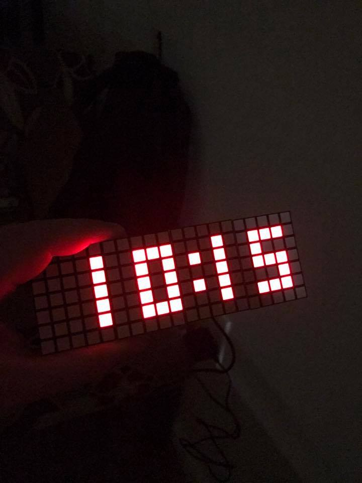
And here's the functioning, finished product! The text pops a lot more here compared to the LCD test photo because of a red filter that's installed in the front of the clock.
I had a blast assembling the Solder : Time desk clock (with the exception of that one piece of acrylic)! Spikenzie Labs has newer, cheaper version of this kit called the Solder : Time LTE with a minimalist case and some extra customizability, so take a look that that one as well!